
Development Log 9 - Building An Inverse Kinematics Walker
Building the Walker
This week, further development focused on Inverse Kinematics (IK) as mentioned in the conclusion of Development Blog 3. The goal was to produce a walking character that can traverse over the generated terrain mesh providing a gameplay interaction between the two procedural contents.
The video by Codeer (2020) provided a simple step-by-step guideline towards implementing a procedural walking animation and served as the guideline for this projects implementation . 1
Figure 1: Highlights of the transform compoenets used to manipulate the mesh.
The red spheres, located under the raised right foot in figure one, are the end effectors (limb) targets point to reach (See Figure 1). When these move, the limbs move too. These targets by default don’t move.
The targets move when a sufficient prescribed distance has been made between themselves and the highlighted green spheres, the predicted target points. These tell the targets where to move and so serve as a prediction of the next step is if a step would be taken.
The targets move to the predicted targets via a Coroutine which lerps their position to the predicted target location.
Figure 2: Demonstration of the ray casted prediction targets determining the next location for the end effector targets.
These predicted targets are projected, (ray-casted) from emitters, seen above with the highlighted yellow cylinder. The emitters are parented to the spider body to ensure the next predicted steps are within reach. These cast diagonally forward and down, allowing for projection of steps onto angled surfaces.
Finally, the highlighted blue spheres provide poles which influence the angles the limbs will bend away from.
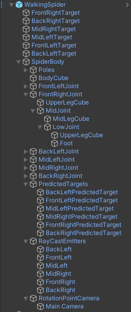
Figure 3: Hierarchy structure of the walker. Top parent contains just input parsing script. The Target components, where the end effectors position themselves too, are not parented under the Spiderbody unlike everything else, to ensure adhesion to the ground.
Figure 4: Current Implementation of FastIK into making a walker via Inverse Kinematics.
With the procedurally animation already in place, further parameters of the above systems mentioned can provide greater procedural animation control via customisation of parameters for the walking cycle:
The offset of the body from the ground.
Leg stride length (per leg).
Leg movement time (lerping time) (per leg).
Movement and rotational speed.
The body of the walker is an offset distance from the average leg placement positions. The body’s rotational positional is a planned implementation also.
One difficultly encountered in the project this entry was implementing an animation curve to influence the arc the legs – its implementation resulted in issues with foot collision on raised surfaces and so was disabled. Furthermore, weaknesses with more complex terrain results in legs / body clipping through surfaces.
With the terrain walker in place, an interactable way of engaging in the procedural terrain has been produced under another topic of procedural content – this author is satisfied with the two implementations of procedural algorithms in isolation. The goal is to merge these two projects into a single scene.
References
Codeer (2020) Unity procedural animation tutorial (10 steps) [YouTube video]. Available at: https://www.youtube.com/watch?v=e6Gjhr1IP6w&app=desktop (Accessed: 7 December 2024)